Tuesday, February 7, 2012

ELECTRICAL HAZARDS

           INTRODUCTION
For both personal and equipment safety, remember that objects made of metal are also conductors of electricity, and as such a short circuit draws maximum current leading to extreme heat and burning.
This means watches; rings, ear-rings, necklaces, cuff links and any other pieces of personal jeweler would put you in danger. If you are injured or cause damage to equipment because of your negligence, you will have to compensate for the damage caused to the equipment. Therefore it is good practice to remove such object before they become a hazard to yourself or equipment.

            Caution notices are used throughout manuals, instructions and maintenance manuals to warn workers of certain processes or steps to follow in reaching the next assembly.
                                                               This will help you to
v      avoid missing important processes in a complicated assembly
v      warn you of a special process that must be performed
v      Warn you of a previously carried out step of some importance in this string of    events.
          Warning notices make the reader aware of a personal safety hazard, to adhere to, or to avoid. These warnings are set in place so you do not get injured by some hazard.
         Remember accidents happen because we become over familiar with a process or from some unforeseen circumstance. Therefore observe warning, caution and any other signs in the maintenance of equipment and work practices.


CAUSES OF ELECTRICAL ACCIDENTS
   v    Unsafe equipment or insulation
v    Unsafe workplaces
v    Unsafe work practices.

Electric shock occurs when electrical energy (current) flows through the body. The amount of current depends on the voltage supplied and the resistance it meets. The effects of electric shock can range from a slight tingling sensation through to death.

                                                         ELECTRIC SHOCK CAN CAUSE

v  Internal bleeding
v  Destruction of tissues
v  Destruction of nerves and muscles
v  Respiratory arrest (breathing stops)
v  Asphyxia (suffocation)
v  Irregular heart beat
v  Death


Thursday, February 2, 2012

            01.Bell 206 jetranger

 
           02.Bell 206 Longranger   
            03.Bell 212


             04.Bell 412
            05. Bell 430

           06.Eurocopter EC120


              07.Ecureuil AS350
            08.Sikorsky S76
             09.Agusta A109 MK11

Wednesday, January 25, 2012

             Helicopters                                                                                                            

      INTRODUCTION    

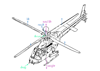
 The main difference between the Helicopter and an Airplane is the main source of lift. Helicopter derives its lift from a rotating aerofoil called rotor. The rotating wing.  Main rotor of a Helicopter has two or more blades depending on the design and size of the Helicopter. Each blade is an aerofoil in design.

  FORCES ACTING ON A HELICOPTER IN FLIGHT

There are four forces acting on the Helicopter. Lift is the force required to support the weight of the Helicopter.

 TAIL ROTOR OR ANTI-TORQUE ROTOR

 According to Newton third law of Motion the torque force applied to the rotor shaft of a helicopter to turn the rotor causes an equal and opposite force which would turn the fuselage of the helicopter in the opposite direction unless measures were taken to prevent it. Tail rotor prevents the helicopter fuselage from turning.

 
HELICOPTER CONTROLS                                                                                                                    
              
                  COLLECTIVE PITCH CONTROL

 Increases or decreases the pitch of all main rotor blades simultaneously. This control is located at the pilots left. To raise the helicopter from the ground, collective pitch is increased, thereby increasing lift to all blades evenly.


                 CYCLIC - PITCH CONTROL

                  Purpose of the cyclic pitch control is to cause tip path plane of the main rotor to tilt, as required to provide for movement of the helicopter in a desired direction.


                    AUTO-ROTATION  
  
                Curve’s contribution to rotating wing machine, paved the way for practical helicopters. He discovered the principle of “autorotation”. This enabled the design of a safe flying machine, which would not stall and crash when its speed through the air was reduced to ZERO.

           The principle of autorotation is that there is a small positive angle of pitch at which the blades could be set to ensure that the rotor would continue to rotate automatically in the airstreams, without an engine to drive it, and still develop enough lift for sustained in flight.


    HELICOPTER CONFIGURATIONS
                      SINGLE ROTOR ARRANGEMENT
  
                     In this arrangement single rotor and a tail rotor is used. Single rotor helicopter is light in weight, But single  rotor machines have limited lifting and speed capabilities and severe safety hazard during ground operations due to the position of the Tail rotor.
                   TANDEM ROTOR HELICOPTER
 
     This helicopter uses two synchronized rotors turning in opposite directions. This design eliminates the need for an anti-torque rotor, since one rotor cancel the torque of other. Each rotor has three blades. This helicopter is capable of lifting large loads.

        SIDE BY SIDE ROTOR HELICOPTER
       Side by side helicopter has two main rotors, positioned out from sides of the fuselage. Rotors turning in opposite direction which eliminate the need for a tail rotor. It has excellent stability and efficient in forward flight.

                          COAXIAL ROTOR HELICOPTER
 
 In coaxial rotor helicopter, fuselage torque is eliminated by using too counter rotating rigid main rotors, mounted one above the other on a common shaft. This has the forward speed more then 250 KN. [129 m/s] Lift load at high forward speed is carried by the advancing blades.

Friday, January 20, 2012

FLIGHT CONTROL

01.LONGITUDINAL AXIS AND ROLLING
                         Longitudinal axis is an imaginary line running through the center of gravity (CG), and is horizontal, when the aero plane is in the attitude of normal horizontal flight. Any rotary motion about this axis is called rolling.
 
              02. NORMAL AXIS AND YAWING
                     Normal axis is straight line through the CG and it is vertical when the aero plane is in the attitude of normal horizontal fight any rotary motion about this axis is called yawing.


         03.    LATERAL AXIS AND PITCHIN
                                                                                                                                                                                                                                                                                                                                   Lateral axis is a straight line passing through the CG, and right angles to the other axis. It is horizontal when the aero plane is in the attitude of normal horizontal flight and is parallel to the straight line joining the wing tips. Any rotary motion about axis is called pitching. 


FORCE IN ACTION IN FLIGHT


            Without taking in to account the force on the tail unit an aero plane, when flying straight and at constant level, it will be under the influence of four main forces.
 
                          01.     LIFT
                       The lift (L) of the main planes acting vertically upwards through the centre of pressure.
 
                                 02.GRAVITY
                The weight (W) of the aero plane acting vertically downwards through the centre of gravity.
 
                                                 03.THRUST
              The thrust (T) of the propeller is pulling force horizontally forward along the propeller shaft.
                  04.DRAG
              The drag (D) is acts horizontally backwards. This is the total drag on the aircraft consisting of the drag on the aero ­foils and also of the remaining parts of the aero plane.


.

AIRCRAFT CONTROL SURFACES


INTRODUCTION

During flight an air plane is rotated about the, three axes by means of the three primary flight controls.


 MOVEABLE CONTROL SURFACE

01.   AILERONS
 Ailerons are primary control surfaces, control aircraft movement about the longitudinal axis used to provide lateral control of aircraft.

 
02.   ELEVATORS
 Elevators are the control surfaces. Which   govern the movement of the aircraft around the lateral axis (Pitch).
 

03.RUDDERS
  Rudder is vertical surface control that is usually hinged to the tail post after of the vertical stabilizer and designed to apply yawing moments to the air plane. 
UNUSUAL CONTROLS
 
 01.    “T”-TAIL 
 “T”-Tail arrangement positions the stabilizer and elevator at the top of the vertical fin.

This design makes the fin and rudder more effective because of the end plate action of the stabilizer location and avoiding the wing turbulence.

 02.  RUDDERVATORS
    Ruddervator are used on V - Tail and the surfaces serve both as rudders  and  elevators. 
 
when the pilot wants to increase the angle of attack, he pulls back the control wheel and both ruddevaters move upward and inward and pushed forward to decrease the angle of attack, the ruddervator move down ward and out wards to turn the air plane to right = right pedal is applied right ruddervator moves downward and out ward, while the left ruddervator upward and inward.


03.  ELEVONS

Elevons are combination of Elevators and Ailerons used on outer tips of some wings. When used as elevators, they both move in the same directions. When used as ailerons they move in the opposite direction, used on all wing air planes or flying wings.


04.  FLAPERONS
 These are ailerons rigged to serve as ailerons or flaps. When use as ailerons, flap Ron moves in opposite directions. When used as flap, flaperons on opposite wings move upward or downward together. ­


                TRIM TAB
Trim tabs are small secondary flight control surfaces, set in to trailing edges of the primary control surfaces.
            The Purpose of trim tabs is to permit the pilot to fly the airplane in a desired attitude, under various load and airspeed conditions without the need to apply constant pressure in any particular direction on the flight controls, this is done by “loading” the control surfaces to a neutral or timed centre position tabs can be fixed or variable.
  FIXED TRIM TABS
 This is normally a piece of sheet metal attached to the Trailing edge of the control surface? This fixed TAB is adjusted on the ground by bending it in an appropriate direction to eliminate flight control forces for a specific flight condition. These are used to adjust Rudders and ailerons of light Aircraft. Fixed tab is normally adjusted for zero control forces in cruise flight adjustment of the tab is trial and error method based on the pilots report..


Thursday, January 19, 2012

AIR CRAFT STABILITY AND CONTROL


Stability of an aircraft means its ability to return to some particular condition of flight (after having been slightly disturbed from that condition) without any efforts on the part of the pilot.

 
               01. STATIC STABILITY
 
An aircraft is in a state of equilibrium when the sum of all the forces acting on the aircraft and all the moments is equal to zero. An aircraft in equilibrium experiences no accelerations, and the aircraft con­tinues in a steady condition of flight. A gust of wind or a deflection of the controls disturbs the equilibrium, and the aircraft experiences accelera­tion due to the unbalance of moment or force.


02.  DYNAMIC STABILITY
 
While static stability deals with the tendency of a displaced body to return to equilibrium, dynamic stability deals with the resulting motion with time. If an object is disturbed from equilibrium, the time history of the resulting motion defines the dynamic stability of the object. In general, an object demon­strates positive dynamic stability if the amplitude of motion decreases with time. If the amplitude of motion increases with time, the object is said to possess dynamic instability.


03.LONGITUDINAL STABILITY
 If the aircraft is stable about the lateral axis, (along the longitudinal axis) it is said to be longitudinally stable.


04.LATERAL STABILITY

Stability is the aircraft about its longitudinal axis (from rolling) is known as lateral stability.